Start with a Fanstel LEW840X, describe the gateway you want, and end with firmware building, flashing and running on it, with a configuration dashboard served from the board’s own flash.
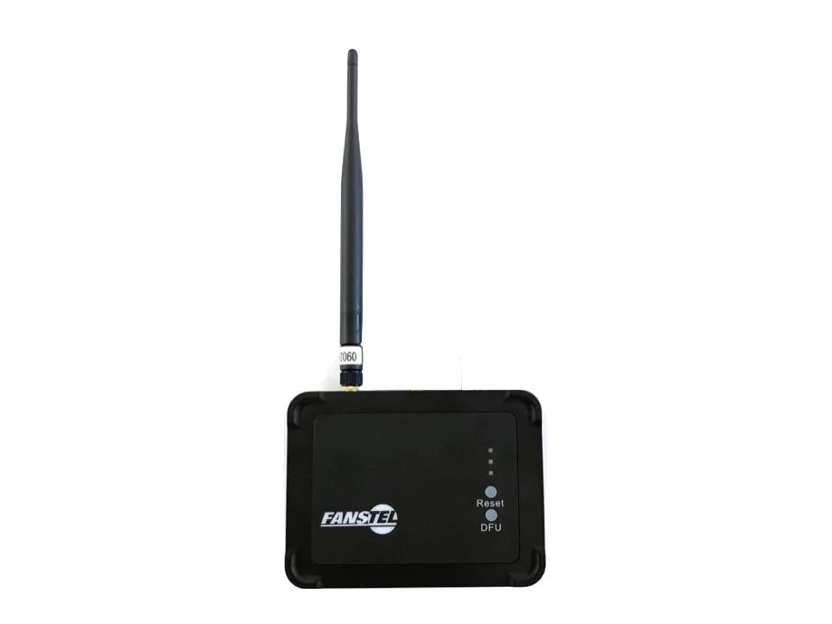
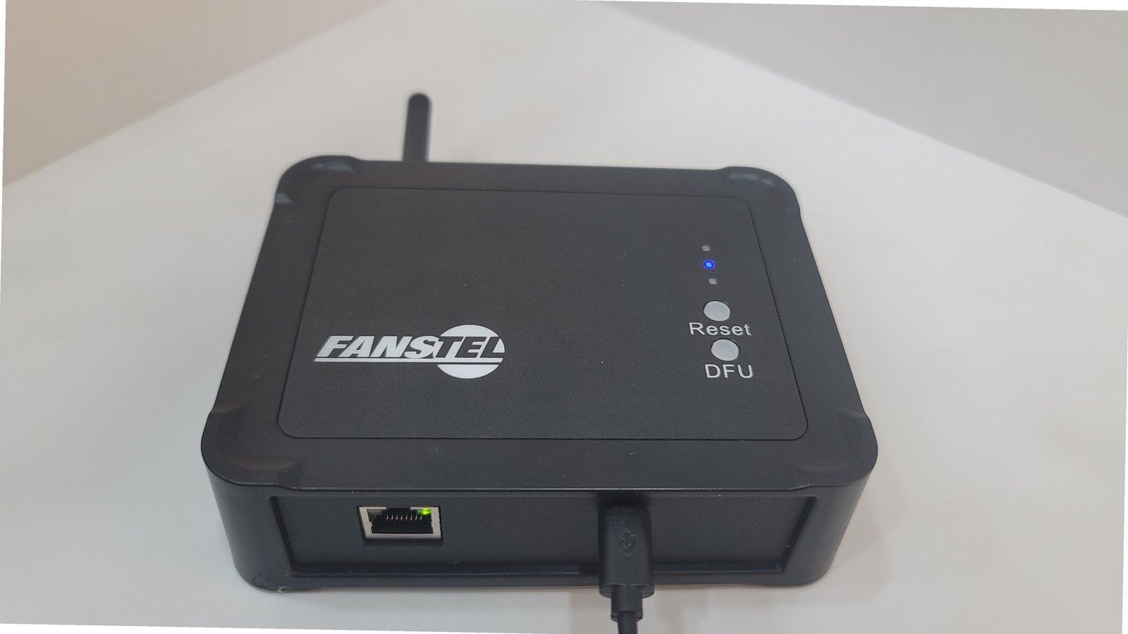
A Fanstel LEW840X industrial IoT gateway, closed

The LEW840X, closed

Real firmware, on real industrial hardware, in one session, without reading a schematic.

The gateway

The LEW840X is a professional IP65 industrial gateway, and a flexible one: the radios sit on M.2 cards rather than being soldered down. Two slots, one for cellular and BLE, one for BLE and LoRa, so a single base covers a wide range of builds, and changing what the gateway does can be a card swap.
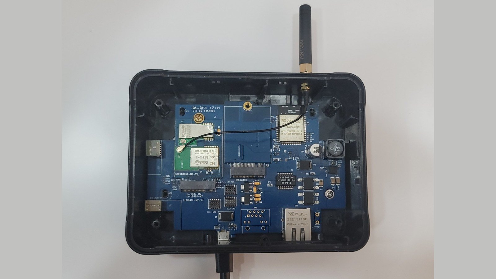
The LEW840X opened, with the M.2 radio card lifted out of its slot and lying beside the board

Open, with the M.2 radio card lifted out. The slot beside it takes a second.

The gateway wired for programming, with the nRF52 DK and the UART bridge both connected

Wired for programming: the nRF52 DK on the debug header and the UART bridge on the base.

The hardware, briefly

The ESP32 on the base owns the network and the application: WiFi, Ethernet and the dashboard. The nRF52840 on the card owns the radio: it listens for Bluetooth Low Energy advertisements, the short packets that beacons, asset tags and battery-powered sensors broadcast to announce themselves. Programming and logs. Two chips means two paths. The ESP32 is reached through Fanstel’s UART bridge board on the base, which is both flashing and its serial console. The nRF52840 on the card is reached over SWD, using an nRF52840 DK purely as a programming probe, with its Debug Out wired across to the gateway’s debug header. RTT rides that same SWD connection, so the radio’s log is there without a second cable.
Which slot the radio sits in decides whether this build is possible at all.The ESP32 has one UART per slot, and on the LN slot the far end is the nRF9160. A BLE module on an LN card therefore talks to the cellular modem, not to the base, so BLE advertisements cannot reach the ESP32 from that slot without modem firmware relaying them. BLE to the base comes from the M2 slot, which is wired straight through.

The prompt

The hardware section names the base and the card, and stops there. No pin numbers and no connectors. The agent already has this gateway’s hardware knowledge, so the prompt is spent on the product you are building rather than on re-typing a schematic.

What the agent does

The prompt pasted in. The whole prompt, before the first response.

1

Plans the system before writing anything

It works out the shape first: which chip owns what, how the two sides talk over the inter-chip link, what the uplink logic has to handle. It shows you that before creating a single file. Read it: this is the cheapest moment to change your mind.
2

Scaffolds both projects

A gateway here is two firmware projects: ESP-IDF on the base, nRF Connect SDK on the card. Both are created in one workspace, each with its own build configuration.
3

Writes the firmware

The dashboard, the network logic, the framed link between the chips, the BLE scanner. It works in passes rather than emitting everything at once, so each part can be checked while the reasoning behind it is still on screen.
4

Builds and flashes, on your board

It builds each side, works through the build errors it hits, finds which boards are actually connected, and knows which connector programs which chip, so flashing is not a step you have to wire up yourself.
5

Reads the board

This is where firmware work stops resembling ordinary coding. The agent captures the ESP32’s serial output and the nRF’s RTT log, and reads what the hardware actually did. Building is not the finish line; a board that behaves is.

Bringing it up

Three states, in order: nothing configured, credentials entered, then running. The captions say what changed between them.
The gateway in access-point mode with the dashboard open, WiFi and MQTT still down

Out of the box. The gateway is its own access point and the dashboard is already served from its own flash, WiFi and MQTT down, because nothing has been told to it yet.

1

Configuration mode

On first power-up the gateway comes up as its own WiFi access point, serving the dashboard from its own flash. Join the access point and the setup page is there, no app, no cable, no internet.
2

Configure, then run

WiFi credentials, the MQTT broker and the BLE filter. Save, and it reboots into running mode: connected, scanning, publishing.
3

Reset, without a cable

Holding the reset button for 5 seconds reboots. Holding it for more than 10 returns the gateway to configuration mode, the recovery path for a unit that was moved to a different network.

The dashboard

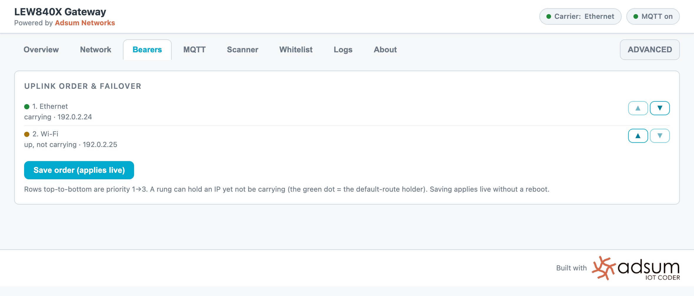
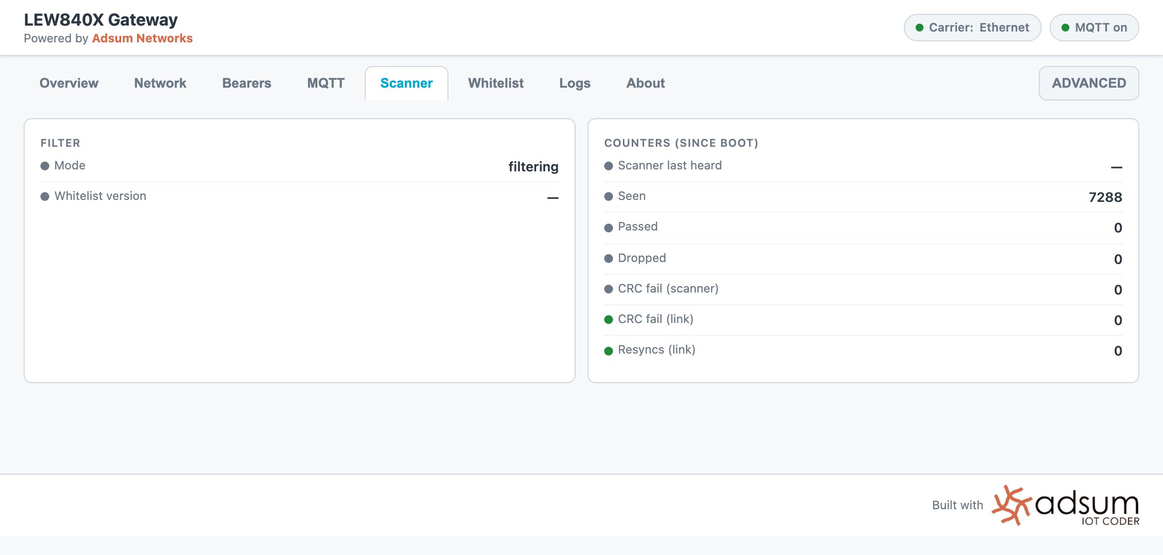
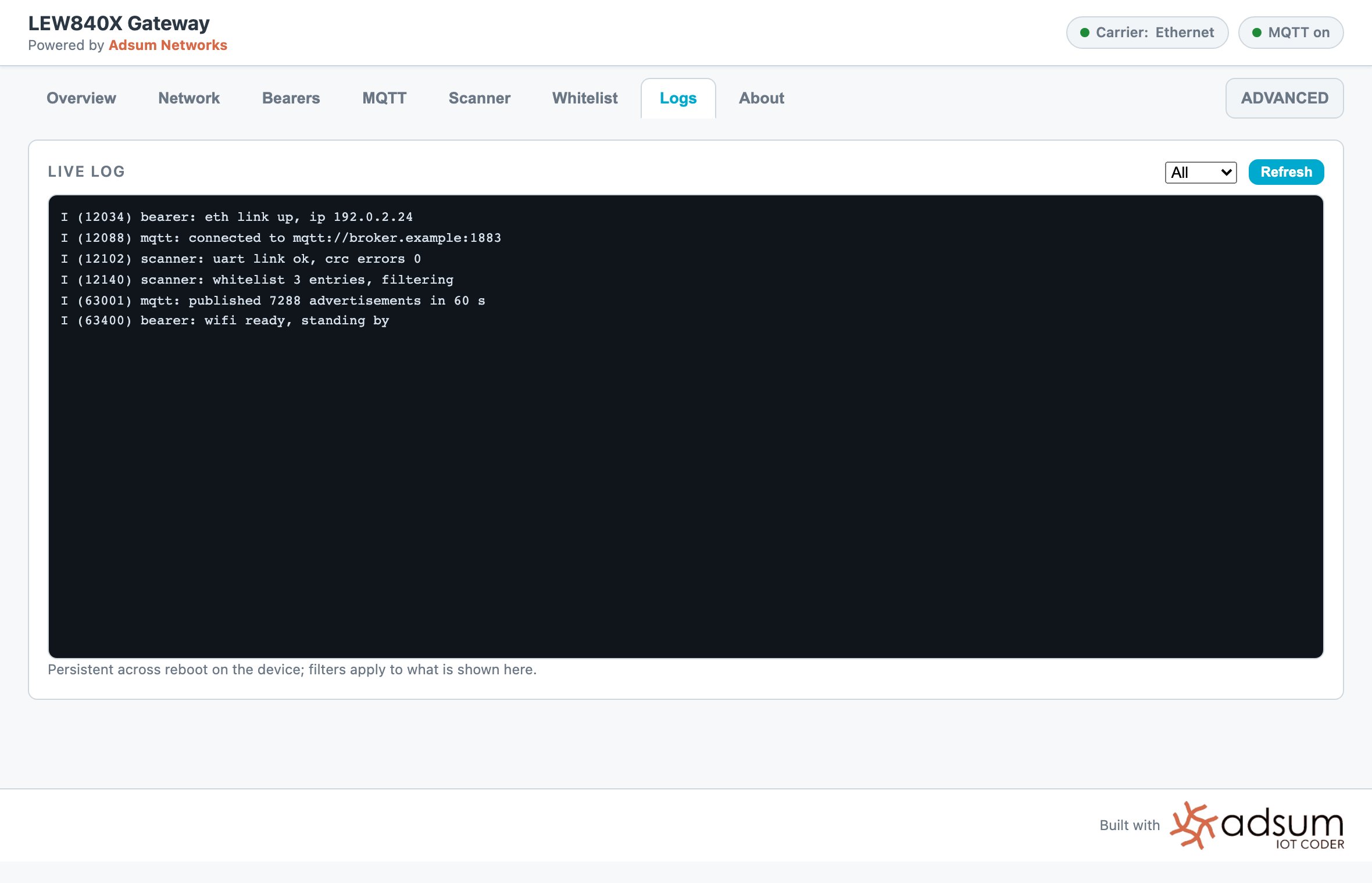
Served from the board itself, with every asset compiled into the firmware, in configuration mode there is no internet, so the page has to stand on its own. Four tabs:
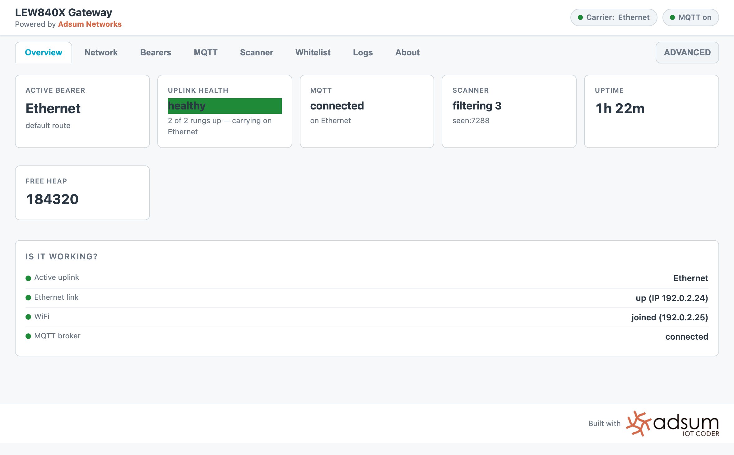
The Overview tab

Overview. Uplink and MQTT status, IP address, uptime and how many devices are being seen.

Live data

The dashboard listing live BLE devices beside an MQTT client receiving the same data Tags in the air, rows updating on the dashboard, messages arriving at the broker.

Where the board knowledge helps

Fanstel builds a lot of hardware, and the range runs wide: bases, enclosures, radio cards, and combinations for most jobs. The cost of that range lands on the firmware engineer: a long specification, a schematic, and part numbers to reconcile before any code gets written. We do that reading once, per product. Adsum’s LEW840X knowledge is curated by engineers, checked against the hardware and refined as we test: which connector reaches which chip, what each M.2 part number actually contains, how the Ethernet interface has to be brought up on this board, and where a printed part number can mislead. It also carries something a parsed document cannot: what has been confirmed on hardware versus what is still only expected, kept separate, so an assumption is named as one rather than presented as fact.

Try it first: the demo firmware

Have an LEW840x on the bench? Register (free) and flash three signed images the agent already knows: a BLE scanner on the nRF52840, a Wi-Fi / Ethernet uplink on the ESP32, and a cellular bearer on the nRF9160. Tags advertising nearby reach your MQTT broker within minutes, so you judge the hardware and the firmware on your own network before writing a line. The limits, before the button: Wi-Fi and Ethernet run without limit; cellular runs in 60-minute sessions; flashing needs nrfutil and esptool on this machine. The signed images are free to flash and evaluate. When the gateway does what you need, the same firmware is available as licensed source, per module, so your team can extend the scanner, the uplink or the bearer on its own: ask from Settings › Account › Request template source. The full picture, row by row, is on gateway firmware. For the cellular card, the flash-only path is its own page: run the LEW840x on cellular from the signed images.

Reproduce it yourself

Prerequisites

  • VS Code with Adsum IoT Coder, from the Marketplace or Open VSX. The free tier needs no key and no account.
  • ESP-IDF for the base, and the nRF Connect SDK with its toolchain for the card. See platforms.
  • A Fanstel LEW840X with a BLE card in the M2 slot (this build used the LORA840XE-M2-V1), Fanstel’s UART bridge for the base, and an nRF52840 DK to use as the SWD probe for the card.
  • A few BLE tags or sensors nearby, so there is something to scan.
No board? The agent works end to end on the bundled samples with the free tier, no hardware and no key required. Bring the gateway when you are ready to flash and verify.

Steps

1

Open an empty workspace

Install the extension, open an empty folder for the project, and open the Adsum panel.
2

Paste the prompt

Paste the prompt with your own hostname, uplink priority and LED wishes. Name the base and the card and stop there; the agent has the pins. Read the plan before it creates a file.
3

Approve the builds, then the flashes

Two projects, two toolchains. Let the agent build each side and work through its own build errors, then approve the flash for each chip: the ESP32 over the UART bridge, the nRF52840 over SWD.
4

Bring it up and watch it

Join the gateway’s access point, configure it from the dashboard, and watch the ESP32 serial log and the nRF RTT log as it reboots into running mode and the first tags appear.

Where this build can go next

The same session can carry on, as the BWG840X build did.

3-layer debug

When the log is clean and the air disagrees: application log, HCI and over-the-air capture, correlated.

CRA readiness

An SBOM from the real build, a ranked CVE scan and a posture check, on the firmware that is running on the gateway.

Verified with