Overview
The hard part of IoT is rarely the hardware. It is the firmware. Off-the-shelf gateways ship as black boxes: you get whatever protocols, cloud endpoints, and update story the vendor chose, and little room to change them. The moment a real project needs custom behaviour, you are writing firmware for two different chips, in two different toolchains, that have to agree on a wire protocol between them. That is where projects stall. This walkthrough follows one project from the launch video. Starting from a single written spec, Adsum IoT Coder built the complete firmware for a production industrial gateway, the Fanstel BWG840, in one working session. The video shows it done in under 30 minutes. The agent planned the architecture, wrote both codebases, built them with the real toolchains, fixed its own build errors, flashed both chips, and verified the result on live hardware. The developer reviewed and approved each step along the way.Adsum is an AI-based coding agent and can make mistakes. It worked from a spec and proposed each step; the developer approved the plan, the builds, and the flashes. This is an assisted build, not an unattended one.
The hardware
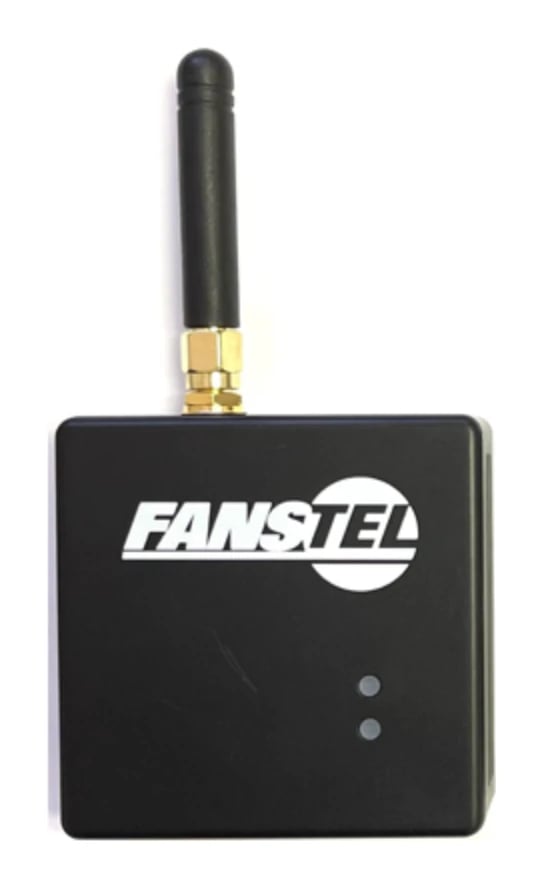
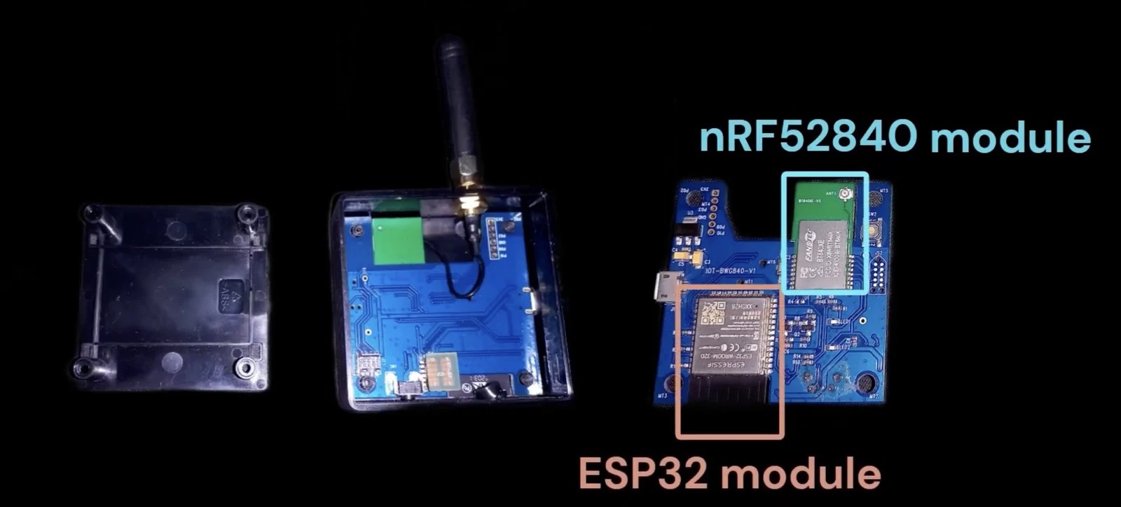
The Fanstel BWG840 (board IOT-BWG840-V1) is a dual-chip industrial gateway. Two SoCs share one board and split the work:- Nordic nRF52840 (BT840XE module, with a SKY66112 power amplifier and external antenna): runs a BLE scanner on Zephyr, using the nRF Connect SDK. It listens for advertisements from nearby BLE sensors.
- Espressif ESP32 (ESP32-WROOM-32D): handles WiFi, the MQTT client, and an embedded web dashboard, on ESP-IDF. It is the uplink to the network and the cloud.
P1.01=RX, P1.02=TX, cross-connected to the ESP32 UART0, GPIO1=TX, GPIO3=RX, via the IOT-JS5 jumper). The nRF52840 is the sensor-facing radio; the ESP32 is the network-facing uplink. Neither chip does the other’s job, and the UART link between them is the seam where a custom protocol has to be designed and kept in sync on both sides.
The SKY66112 power amplifier is not optional. It must be initialised through the nRF PA/LNA config (
PA=P0.17, LNA=P0.19, CPS=P0.06, CHL=P0.08), or the radio range collapses. TX power is capped at +2 dBm (FCC) and -4 dBm (CE). The status LEDs and button are all active-low: blue LED1 on P0.11, red LED2 on P1.00 (which doubles as SWO, so trace must stay disabled), and the button on P0.16.Flashing the two chips
They flash by different paths, and the inter-chip UART matters here:- ESP32: the IOT-UART-ESP-V1 bridge board replaces the jumper (JS2 connector is PC-to-ESP32), and
idf.py flash monitorauto-programs. While the bridge is in, the two chips are disconnected from each other. - nRF52840: SWD over the TC2050 Tag-Connect pads into a nRF52840DK Debug Out (
west flash). RTT logs stay available even with the jumper installed, so the nRF side is observable during integration.
Data flow
The path a single reading takes, end to end:- A BLE sensor broadcasts an advertisement.
- The nRF52840 scanner (Zephyr) receives it and forwards every advertisement (MAC, RSSI, raw payload) downstream. It does no filtering.
- The nRF52840 sends it across the UART bridge as a framed packet (start byte, length, and CRC).
- The ESP32 (ESP-IDF) validates the frame, filters by the configured MAC whitelist, and publishes to MQTT (a topic per device MAC), in either a RAW hex or a PARSED payload mode.
- The reading reaches the MQTT broker, and in parallel is visible on the ESP32’s embedded web dashboard at
http://bwg840-XXXX.localover the local network.
Architecture
The end-to-end flow, from BLE advertisement to MQTT, covering first-boot provisioning, the continuous scan loop, the button config reset, and the WiFi-fail fallback: The build produced two separate firmware projects that agree on one wire protocol:- BLE scanner (nRF52840, Zephyr / nRF Connect SDK): a continuous, deliberately simple scanner that forwards every advertisement (MAC, RSSI, raw payload) downstream. All filtering lives on the ESP32 side, so the radio stays reliable and dumb.
- UART framed-packet protocol: a framed byte protocol between the two chips, with a start byte, a length, and a CRC, so the ESP32 can reject corrupt or partial frames rather than trusting the bus. It also carries a status frame, so both chips share the gateway’s global state (which drives the LED table below). Never raw prints between the chips.
- First-boot provisioning (ESP32, ESP-IDF): on an empty NVS the ESP32 comes up as a WiFi Access Point (
BWG840-XXXX, derived from its MAC) serving a setup dashboard for WiFi credentials, the MQTT broker, the sensor MAC whitelist, and the payload mode. Save and reboot persists to NVS and switches to Station mode. - Embedded web server and dashboard (ESP32, ESP-IDF): in Station mode the dashboard stays reachable over mDNS at
http://bwg840-XXXX.local, with Status, Config, and Live Logs tabs. It is a dark, card-based UI with all assets embedded in the firmware, so it renders perfectly offline in AP mode where there is no internet, and it is usable from a phone. - Two payload modes: readings publish as RAW (a JSON of MAC, RSSI, timestamp, and raw advertisement hex) or PARSED (decoded standard BLE AD structures: device name, TX power, manufacturer ID, iBeacon, Eddystone, service data). Parsing is generic BLE only, with no vendor-specific decoding.
- MQTT client with reconnect and backoff (ESP32, ESP-IDF): the cloud uplink, written to survive a flaky network by reconnecting with backoff rather than giving up on the first drop.
- Button config reset: a 10-second button hold makes the nRF52840 send a config-reset frame, and the ESP32 returns to AP mode with the previous config pre-filled as placeholders, so a single field can be changed and saved. Both LEDs flash three times to acknowledge.
- Resilience and logging on both sides: hardware and task watchdogs, reconnect and backoff throughout, and a WiFi-fail-to-AP fallback so bad credentials never brick the gateway. Logging stays at INFO and rate-limited, with no per-advertisement printing in normal operation, and DEBUG enabled only per module when something needs a closer look.
LED status
The two on-board LEDs report state, with blue for mode and connectivity, and red for problems only:The prompt
This is the complete spec used in the video. Copy it, adapt the board and behaviour to your own project, and run it in the extension.Professional BLE-to-WiFi Gateway (Ep1)
What the agent did, step by step
1
Loaded curated firmware knowledge
The agent pulled the relevant human-curated knowledge for the task: nRF Connect SDK and Zephyr for the scanner side, ESP-IDF for the WiFi and MQTT side. This is the engineering knowledge that grounds what it writes, loaded per task rather than guessed.
2
Planned the architecture
It laid out the two-project split, the UART protocol between them, and the data flow from BLE advertisement to MQTT, and presented the plan for approval before writing code.
3
Wrote code for both projects
It wrote the nRF52840 BLE scanner on Zephyr and the ESP32 WiFi, MQTT, and web-dashboard firmware on ESP-IDF, including the shared UART framing on both sides.
4
Built with the real toolchains
It built each project with its actual toolchain, the nRF Connect SDK build for the nRF52840 and the ESP-IDF build for the ESP32, not a mock or a simulation.
5
Self-corrected build errors
When a build failed, it read the compiler and toolchain output, found the cause, and fixed the code, then rebuilt until both projects compiled cleanly.
6
Flashed both chips
It flashed the nRF52840 and the ESP32 on the Fanstel board.
7
Verified on hardware
It confirmed the end-to-end path on live hardware: a BLE reading arriving at the nRF52840, crossing the UART bridge, and being published by the ESP32 over MQTT, with the dashboard reflecting it.
Reproduce it yourself
Prerequisites
- VS Code
- Adsum IoT Coder, from the Marketplace or Open VSX. The free tier needs no key and no account.
- nRF Connect SDK and its toolchain, for the nRF52840 side. See platforms.
- ESP-IDF, for the ESP32 side.
- A Fanstel BWG840, or any comparable dual-chip board pairing an nRF52 with an ESP32 over UART.
No board? You can still see the agent work end to end on the bundled samples with the free tier, no hardware and no key required. Bring your own board when you are ready to flash and verify.
Steps
1
Install the extension and open a workspace
Install Adsum IoT Coder, open an empty folder for the project, and open the Adsum panel.
2
Paste the spec
Paste the prompt above, adapted to your board and behaviour, and let the agent plan the architecture. Review the plan before it writes code.
3
Approve the build for each chip
Let it write and build both projects with their real toolchains. Approve the builds, and let it self-correct any build errors.
4
Flash and verify on hardware
On the BWG840 the two chips flash by different paths: the ESP32 over the IOT-UART-ESP-V1 bridge with
idf.py flash monitor, and the nRF52840 over SWD with west flash, with RTT for its logs. Approve the flash for each chip, then confirm the BLE-to-UART-to-MQTT path on live hardware, watching the nRF RTT logs and the dashboard Live Logs tab.Links
- Video: youtu.be/WrRYutpmHi8
- Source and issues: github.com/adsumnetworks/Adsum-IoT-Coder
- Install: VS Code Marketplace or Open VSX